28 November 2024
Quickly estimate the planing vessel resistance

How to calculate the vessel resistance? Quickly estimate the planing vessel resistance through this empirical method.
Table of Contents
Definition
Note that, resistance estimation for a vessel comprises a fundamental exercise in the design of the vessel. Specifically, resistance is a property that depends on the vessel’s hull. For instance, a conventional commercial vessel with a bulbous bow will carry completely different resistance characteristics compared to a high-speed planing vessel.
Therefore, naval architects are using various methods to estimate vessel resistance as per the below list.
- Hydrodynamic modeling/CFD analysis;
- Model testing for accurate estimates;
- Empirical relations in the preliminary design phase for a fair estimate of the resistance;
However, empirical relations also vary depending on the vessel’s type. Despite the Holtrop-Mennen method being the most popular, used for conventional ship hulls (usually merchant vessels), it does not apply to high-speed hulls and planing boats.
Planing Vessel
We can distinguish a planing vessel from a conventional displacement vessel by the mechanism of weight support. Note that, for a displacement vessel, the buoyancy force supports its weight. But, a planing vessel supports its weight by the hydrodynamic lift forces generated when the vessel moves at high speed over water.
During the time that a planing vessel is at rest or at low speeds, buoyancy supports its weight. Thus, as it moves at a higher speed, the hull shape generates hydrodynamic lift forces to fully support the hull. In some crafts, the lift and buoyancy both support the weight.
Resistance Estimation
Considering the above, this article will cover a theoretical approach to estimating a planing craft’s performance. Note that, a number of resistance tests have been performed by Savitsky (1964) to determine the formula for the lift and drag of planing vessels, and empirical relations have been provided for the drag.
In this method, at equilibrium, part of the lift is generated by Buoyancy while the rest is generated by the hydrodynamic lift. The basic parameters of the vessel (i.e. dimensions, speed, displacement, etc.) are taken as inputs, and hull parameters (i.e. trim angle, wetted length of the keel, etc.) are determined. Then, the parameters will be used to determine the resistance of the vessel.
Step 1 – Displacement Froude number
The first parameter to be calculated is the displacement Froude number. It is defined thus
Where,
V is the speed in ft/s (knots * 1.6889);
g is the gravitational acceleration, 32.2 ft/s2;
DV is the volume displacement in ft3;
Step 2 – Froude number based on ‘b’
Note that, b is the maximum beam of the vessel over chine or spray strips. Usually, it is the beam of the planing area of the vessel or at the waterline.
Step 3 – Equivalent flat plate lift coefficient
Step 4 – Lift coefficient for a finite deadrise
Depending on the deadrise angle β, the lift coefficient for a finite deadrise is calculated from the flat plate lift coefficient as per the following formula.
Step 5 – P/B Ratio
Furtherly the P/B ratio shall be calculated, considering that P is the distance from the aft of the vessel to the longitudinal center of gravity (LCG).

What are the Tests & Trials that a ship undergoes?
Both a merchant and a naval ship require extensive tests and trials in order to handle the weather conditions and operational challenges.
Ship Nerd
Step 6 – Mean wetted length-beam ratio:
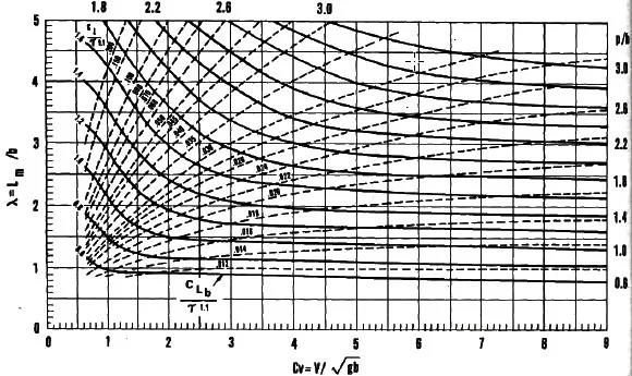
The mean wetted length-beam ratio λ, shall then be obtained from Koelbel’s curves as per below figure.

Step 7 – Trim of vessel in Equilibrium
Then the vessel’s trim in quilibrium is calculated by using the Savitsky formula as follows.
Where,
τ is the trim angle, deg;
λ is the mean wetted length-beam ratio as per Step 6;
Step 8 – Keel-wetted length ratio
Calculate the keel-wetted length ratio following the formula below.
Step 9 – Is the vessel fully planing?
Check whether the vessel is fully planing with the following relation.
If the relation is true then the vessel is fully planing, i.e., the bow is clear of water, or else it is not. If it is fully planing, then the method is valid. Otherwise, this method is not applicable for vessels not fully planing

SEEMP Part 3 – Easy compliance for 2023
Shipowners rush to calculate the attained CII Rating of the fleet to include in SEEMP Part 3 when it is not needed. Why?
Ship Nerd
Step 10 – Vessel Resistance
At last, the estimation of the planing vessel resistance can be obtained from the following expression.
Where,
W is displacement;
CFO is calculated from ITTC Line, using the following formula;
With, Rnb as follows;
And,
Summary
Overall, the resistance of a vessel holds immense importance in the design stage of a vessel. Therefore, Ship Nerd has put together the above 10 steps to quickly estimate the resistance following the empirical method. It is recommended to seek professional advice before executing any activity which draws on the information mentioned in this post.
Source: Principles of Naval Architecture Second Revision, Volume II Resistance, Propulsion and Vibration read more
See Also

CII Calculation: Carbon Intensity Indicator Guide
How to calculate the CII rating? We debunk its complexity by simplifying the procedures based on IMO guidelines.


